The Ultimate NES Mod
aka:
A fully Emulated Nintendo Entertainment System!
Tutorial written
by: Mr. Chips
Back to page 1
Page
2
onto page 3
The
Nitty Gritty:
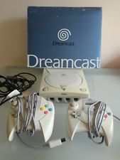
Grab the Dreamcast. Take off the
modem. Take out the 6 screws, take off the cover. Start removing everything. Keep
the GD-ROM, Power Supply, Motherboard and controller ports all together and intact.
They may seem flimsy, because they don't have any screws holding them together.
I suggest keeping the plastic guard between the power supply and mobo plate, as
well. Set the dreamcast case + screws aside.

Take a
look at the corner of the DC assembly.

That non-locking switch is what tells the dreamcast
whether the lid is open or closed. When you open the lid, the DC assumes there
is no Disc. Because there is no lid, we will have to tape it down. Otherwise you
cannot play any games.

Tape it like so. Use as much tape as you feel you
need to hold it in place. As always, careful not to touch the lens.

Then twist that clip off. A pair of short pliers will
work best, but I used needle-nosed. Also, pull off the metal shield around the
A/V and serial motherboard connections.
Next you should take
a look the DC power switch. Here it is.

Notice that the DC and NES switch are fairly similar.
They are both of the Normally-Open (NO) variety. The only major difference is
that blue capacitor.
So, you will need to transport it over the
the NES switch pronto!

Just like that, kiddies!
The amazement
does not stop there...
It seems that the Nintendo was MEANT to
house this younger, but beefier console!
See that power plug?
Well as you can tell from my pic here, I have cut it into two, seperating the
Brown and Red from the other wires. And it will fit perfectly on the DC's power
supply. What a great feeling it is, when similar parts save you time and work!

Then just
desolder out the old NES LED, and put it away. It does not have the same power
rating as the Dreamcast's. Next desolder the DC's LED. So you have the option
of using a new blue LED =), or the old orange DC LED. It is a matter
of wiring. Take a look below, at the bottom of the DC controller port PCB.

Obviously, the white and orange wires are for the
LEDs. Well, the white wire is also ground for the "reset" switch too. But the
orange is the LED's anode (or positive +). A simple way to wire it would be to
use the existing LED holes, however I burnt mine and broke a trace. So I just
followed the trace to another suitable solder point.
Bring your
DC guts over the NES case. Try fitting it, and making adjustments until it sits
as low as possible, with the connections as close to the side of the case as you
can. Also screw the NES power switch back in first of all. It will have to fit
or else, no dice. This is also a good time to measure where your A/V and power
wires will go through the side of the case. Go ahead and cut them out with a dremel,
just be sure to mark it first with a knife or X-acto. Make sure the A/V cable
in in firmly. Of course, do not actually plug the machine into any outlets at
this point.
"The SIDE?!", you say?
Sure, it
isn't such a bad thing, the original NES had it's RCA jacks sticking out the side
anyways. It will have to do, this seems to be the best way to arrange the Dreamcast
parts.

It should be
oriented like so.
DO NOT glue anything in place yet.
But
I reccomend you glue the fan by the holes in the position shown. sticker facing
outward, just like in the DC. Is it effective in this position? I'll let you know
when mine overheats :P
Lastly, If any wires are hanging out
in awkward positions, tape or glue them so that they arent. Also, I recommend
taping the GD-ROM top section to the base. This will keep it from falling out
when you turn the machine upside down or on it's side to put in / take out screws.
Just dont put tape on the laser, track or motor, obviously.
Controller
Installation / Wiring:
site here:
http://devcast.dcemulation.com/mods/nes/nes.php
One
important thing about this tutorial. It was written for NesterDC 5.0 which had
the NES_B as DC_B. You must connect the NES_B to DC_X for NesterDC 6.0!!
You
cannot alter this is the "options" menu since you would have to hook up a regular
DC controller everytime you powered it up to change it, not to mention you would
need to cram in a memory card as well. Just do it this way, and you won't have
to go back and redo it as I did.
Basically it will tell you
how to wire up the NES controller to the DC controller. The only difference with
this mod to The Ultimate NES Mod, is you will need to shorten the DC wire, and
leave the controller's PCB board out of it's plastic. Take off the triggers as
well.

Make the wire about this short. Leave a little if
it make you feel confortable. For a secure connection, use solder instead of twisting.

here is an example of a very small DC controller
which should work nicely if you are concerned about space. However, wiring will
not be straightforward. A regular Sega controller is recommended. But it can be
difficult to fit in 2 of them.
Once you have done the wiring,
you will need to have a way to get back to the menu to choose a game. Restarting
the system itself takes too long, and would not be practical since the Dreamcast
has no obvious reset ability.
In NesterDC, to exit to the menu
you must hold both triggers and start. This is not possible with the 9 button
controller you have, so you will need to wire up the NES' "RESET" button to act
as both triggers. Then, when you are using The Ultimate NES Mod, you can get to
the rom select screen through pressing Start+Reset simultaniously. It takes some
tweaking, but these are the easy steps you must take.
1.
Take
out the Power/Reset PCB again.

Make the scratches you see here.
2.
Then
you must solder a wire to the contact shown above (green) with 2 wires attached
at the end. It should be around 10 inches or more. Keep it all as one color to
avoid confusion. Screw the PCB back down with the wires hanging freely.
3.
Attach
the wires you just made to these contacts.

(image taken from NES controller tutorial and altered
without permission, sorry :)
The other wire which is yellow can
be connected to ground such as the one shown.
That's it for the
controller :)
If you want to fit another one, do this again and
cram it in somehow. I haven't tried it yet but will in the near future.
The Hottest DCEmu Posters
|